Equipment List:
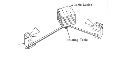
Pasco Microwave Optics including the mock crystal cubes and rotating
table.
Purpose:
To calculate the 100 plane spacing in a mock crystal using Bragg
diffraction.
Introduction:
See page 1011 of Halliday, Resnick, and Walker's 7th edition.
See this link: Bragg
Diffraction
Procedure:
Set up your equpiment and get it working properly.
Data:
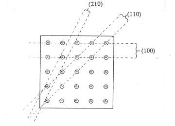
Remember you are trying to record the grazing angle not the angle of
incidence
to the normal as is more common.
Remember ALL your data must always be taken where the angle of the
transmitter
is the same as the angle of the reciever. The receiver is always to
measure
the relected beam from the transmitter and as such, those two angles
(incident
and reflected) must be the same. For this reason, after starting out
with
the transmitter and receiver directly facing each other (with the cube
in
between), you proceed to take the data by moving the tranmitter (it has
the
longer electrical cord) TWO degrees and then the rotate the crystal in
the
same sense but only by ONE degree. This will ensure that your reciever
is
always measuring the reflected angle from the transmitter of the 100
plane.
Take between sixty and seventy data points.
Anaysis:
Graph the intensity versus grazing angle; use the computer. Your will
find two orders (m=1,
m=2) for which there are maxima. The first order maximum will be the
largest
of the graph. The second order maximum will be much smaller. There will
be
other minor maxima from errant reflections. Find the angle of the first
and
second maxima from your graph and calculate the spacing. Compare to a
direct
measurement with a ruler or vernier calipers. If all goes well, you
could get a one percent discrepancy; more than ten percent and
something may be wrong.