Equipment List:
zener diode
300 - 600 ohm resistor
bread board
DC power supply
HP DMM (as the ammeter)
Hand held DMM (as the voltmeter)
assorted bananas and alligators
Procedure:
An ideal diode allows current through it in only one direction. Consult your
instructor as to how this is accomplished with a PN junction. Construct a
circuit similar to the light bulb lab. Meausure the voltage across the diode
as the current through it increases in reverse as well as forward bias. Take
twenty data points. Plot the charateristic curve on the computer. Make sure
the horizontal (voltage) axis is in increments as fine as at least 0.5 V.
In reverse bias, let the voltage and current values be negative. Consult
your instructor on the maximum voltage across the diode before it fails.
Often a zener diode's maximum voltage is near the threshold voltage. The
diodes provided by De Anza are typically rated somewhere between 1 to 5 watts.
To calculate the power dissipated by the diode, to check if it is operating
within the acceptable range, use the relation P = I V.
Analysis:
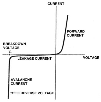
The threshold voltage (in forward bias) is 0.3 volts for germanium and 0.7
volts for a silicon diode. The zener voltage (the threshold voltage for a
zener diode in reverse bias) is stated on the small package your diode came
in. By examing your graph, roughly determine whether the diode is a silicon
or germanium type. Also determine the zener voltage for your diode.
Web References:
Diode
(http://www.americanmicrosemi.com/tutorials/diode.htm)
Zener diode
http://www.americanmicrosemi.com/tutorials/zener.htm