Equipment List:
Pasco E/M set-up
Cenco power supply
assorted permanent magnets
tensor lamp
assorted bananas
meter sticks
Purpose: To explore the trajectory of moving charge in a uniform magnetic and to calculate the ratio of the charge of an electron to its mass.
Background: This experiment duplicates the results obtained in 1897 by J.J. Thomson, the "discoverer" of the electron. At that time no one could measure the value of the charge of an electron or its mass as isolated quantities, but by a relatively simple experiment one could measure the ratio of the electron's charge to its mass, E/M, and knowing this much is useful and better than nothing.
Theory: A detailed discussion of the theory of a similar
experiment
can be found in Tipler's 5th edition physics text, page 837.
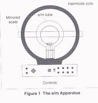
Refer to the figure above during the following discussion.
If all three vectors are mutually perpendicular to one another, the magnitude of the force on a moving charge within a magnetic field is given by:
KE = eV
The magnitude of the magnetic field produced by the Helmholtz coils in terms of the current I:
B = [NuI]/[(5/4)^3/2 a]
From Newton's laws and circular motion we know:
e/m = [2V(5/4)^3 a^2]/[NuIr]^2
Introduction:
In this experiment two devices are used, a CRT (cathode ray tube) also
known as an "electron gun" and a special arrangement of two identical
coils
of wire separated by a distance equal to their radii, Helmholtz coils.
The CRT produces a beam of electrons within a glass tube filled with
low
pressure Helium gas (10^-2 mm Hg). The kinetic energy of the electrons
in the beam (and therefore their speed) can be determined by knowing
the
"accelerating voltage" of the CRT tube. The special geometrical
arrangement
of the Helmholtz coils produces a uniform magnetic field when a current
passes through the coils.
The apparatus provided by Pasco contains the CRT and the Helmholtz coils together on one stand. In this experiment both of these devices, the CRT and Helmholtz coils, are controlled by the Cenco power supply.
The CRT needs two sources of power; one source supplies a small AC voltage of about 6.3 volts to the heater element which "boils" the electrons from the cathode plate (this process is called "thermionic emission"). The electrons are next focused into a beam by the second power supply for the CRT, the accelerating voltage, which is a DC source of between 150 and 300 volts. The higher the accelerating voltage the longer the beam becomes.
Procedure:
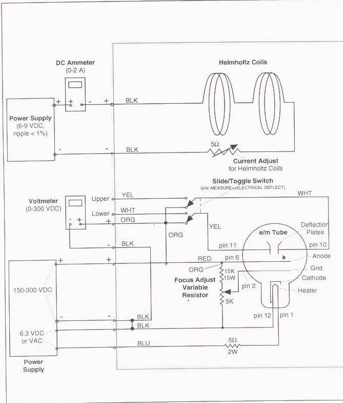
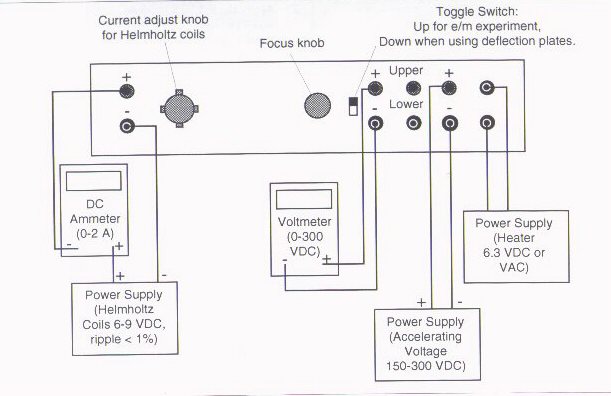
1. Connect your Cenco power supply to the E/M apparatus as shown in the diagram below. The Cenco power supply sends two voltages to the CRT and one voltage to the Helmholtz coils.
|
THINGS TO BE
CAREFUL ABOUT!
The heater element for the CRT must not exceed
6.3 volts
AC.
The accelerating voltage for the CRT should not exceed 300 volts DC. The current through the Helmholtz coils must not exceed 2 amps. The electron beam from the CRT heater element must not be allowed to touch the glass containing bulb for an extended time. |
2. Make sure all the power dials are turned to their zero level and
then turn the Cenco power supply on. The AC heater voltage is
automatically
turned on to the correct voltage; after about two minutes you should
see
the heater filament inside the tube glow red indicating that it is
heating
up correctly. Note that you can rotate the tube by gently
turning
it at its base; do not be afraid of holding the tube, as long as you
don't
grab it too tightly you will not break it and there is no danger of an
electrical shock around the tube. Do not remove the bulb by lifting
it from its holder!
| NOTE: There are two meters on the front of the Cenco power supply. The meter on the left is a voltmeter and measures the accelerating voltage. The meter on the right is an ammeter and measures the current through the Helmholtz coils. Remember, these two meters measure different power supplies. |
3. After you have observed the reddish glow of the heater filament, you can turn up the accelerating voltage to about 150 volts and produce a bluish colored, straight beam. If you apply enough voltage the beam will hit the side of the glass tube; don't let the beam strike the glass for a long time as it will eventually wear a hole in the glass tube! (And the glass tube is quite expensive.)
4. Rotate the glass tube so the beam moves out toward you. Take the permanent magnet and move it near the beam. Note how the beam deviates under the influence of a magnetic . Increase the accelerating voltage (but no further than 300 volts!) and continue to play with the permanent magnet. Knowing the structure of the magnetic for a permanent magnet, see if you can confirm the three step right hand rule relation between the magnetic field, the velocity of the charge, and the magnetic force on the charge.
5. Now you will create a magnetic field with the Helmholtz coils and this will deviate the beam; you no longer need the permanent magnet. Make sure the slide switch near the focus knob on the E/M apparatus is pushed up to the E/M position. Turn up the power to the Helmholtz coils (no more than 2 amps on the meter). There are two dials that control the current to the Helmholtz coils. One dial is on the left front of the E/M apparatus and is labeled "current adjust knob for Helmholtz coils"; turn this dial to a "nine o'clock" position and leave it there (turn it back to zero when you are finished with the experiment). The second dial is found on the left front of the Cenco power supply; this is the dial you will use to adjust the current to the coils. After you turn the current up to about 1 amp, the beam should deviate from its normally straight line path. Do not turn this current to more than 2 amps. Rotate the tube and note the helical trajectory of the beam; see if you can explain the nature of this trajectory.
Performing the experiment:
1. Rotate the glass tube so that the circular beam is parallel to the
mirrored ruler behind it. When this is so, the beam will not have a
helical
trajectory, only a circular one.
2. Adjust the accelerating voltage and the Helmholtz current until you achieve a full circle beam trajectory where the horizontal diameter of the circle is just in front of the mirrored ruler. The zero value on the ruler should be at the center of the circular beam, if that is not so, adjust the accelerating voltage and Helmholtz current until it is correct. You may also use the focus knob on the E/M apparatus to enhance the visual quality of the beam. Record the values of the accelerating voltage and the Helmholtz current that produce the best circular trajectory.
3. Now measure the radius of the circular beam. This is not easy because the beam disperses and is not just a thin line. To increase the accuracy of your measurement, measure the radius on the right side of the center of the circle and the left side and take an average value. Due to the sum of many systematic errors, it turns out that you should try to measure a larger radius than a smaller one if you have the choice.
Use the mirrored properties of the ruler to minimze parallax error. To use the mirror, align the image of the beam with the real beam and then read the position on the ruler.
4. Measure the radius of one Helmholtz coil, a, with the meter stick.
Calculations:
Given the value of the charge of an electron e = 1.60 X 10⁻¹⁹
coulombs and the electron's mass m = 9.11 X 10⁻³¹
kilogram,
calculate the value of E/M to three significant figures. Call this
value
the accepted value.
Using the equation derived in the theory section above, calculate the value of E/M from your four measurements: the accelerating voltage, the Helmholtz current, the average radius of the beam, and the radius of one Helmholtz coil.
As well, calculate the value of the magnetic field in teslas. Compare this value to the earth's average magnetic strength, 0.5 gauss (where 1 gauss = 10-4 tesla). Does the Helmholtz magnetic field have to be greater than the earth's in this experiment?
Conclusion:
Discuss the accuracy of your results and ways to minimize or eliminate
any systematic errors.
Tips:
Measure the outside radius of the beams trajectory to minimize
systematic
errors.
Keep the accelerating potential above 250 volts.
Try for a beam radius of around five centimeters.